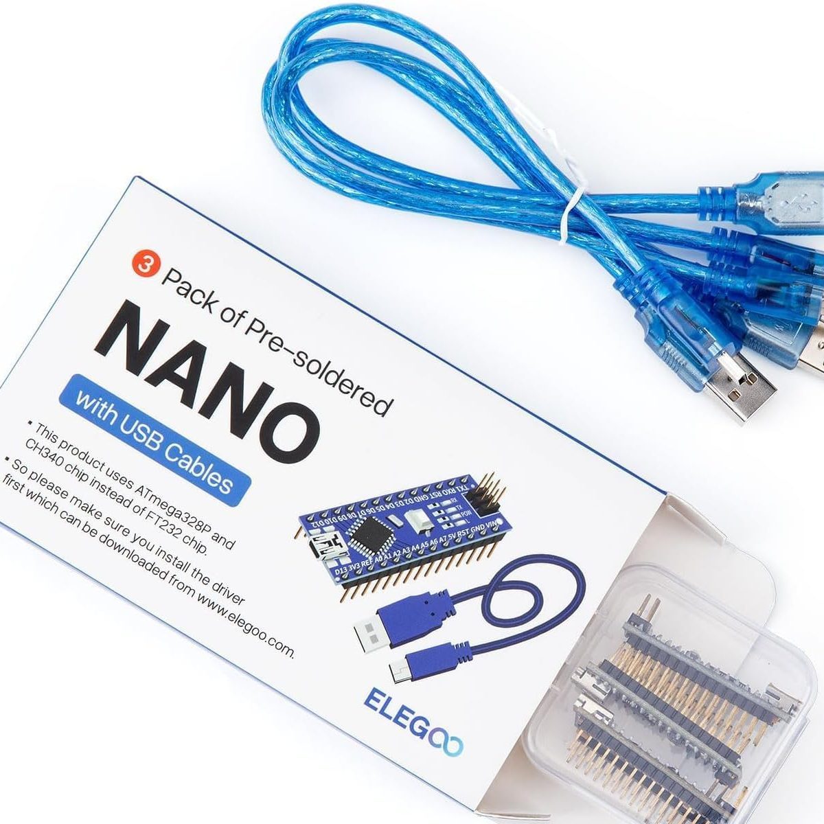
Arduino Nano
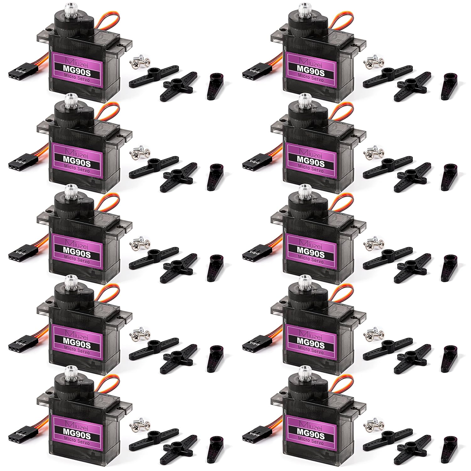
6 Servos
Movie Accurate
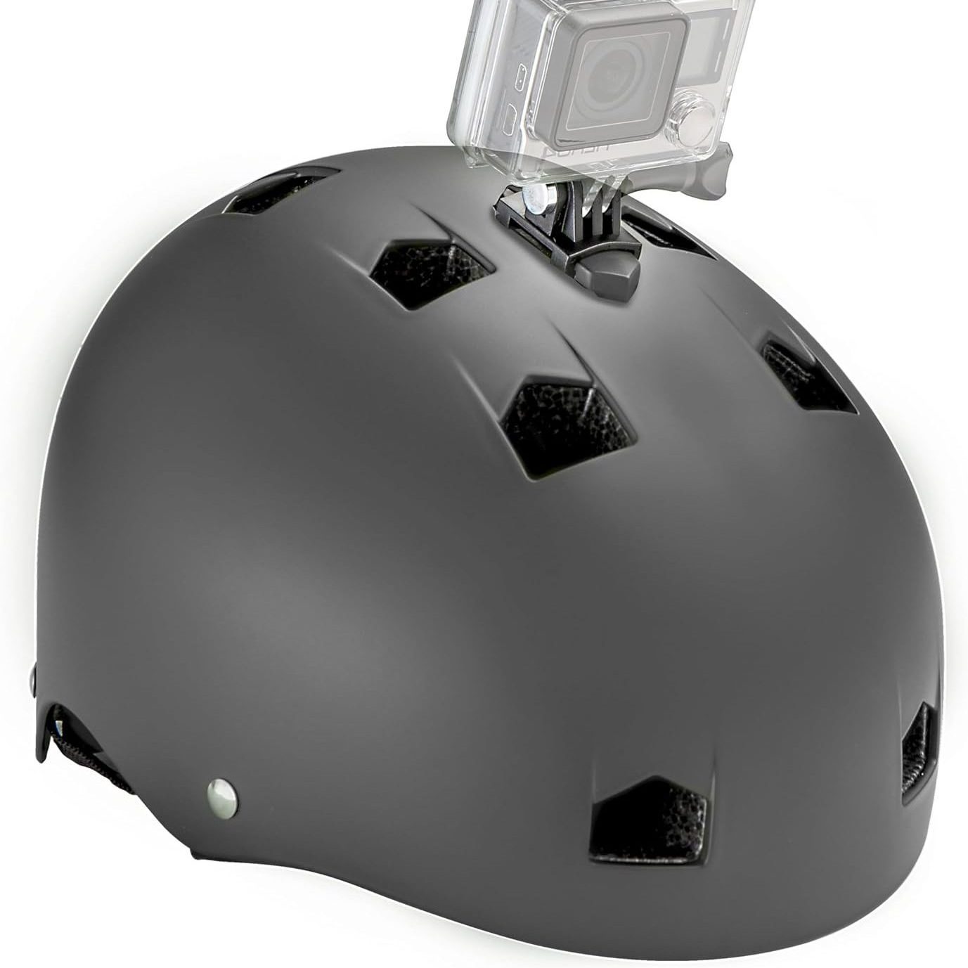
Bike Helmet
The CAD Process
Model Iteration
Over the span of a month, I designed over a dozen versions of my helmet in OnShape, each with increasing detail and cleaner design. I used 4 reference images of the front, side, and top, as well an isometric view for details
Final Design
I used a open source head shape model to size my helmet. The final design has a tri-split front face, and a detachable chin to make it easier to wear. The front will have cut out holes for visibility.
Pre-Printing Tweaks
My original model turned out to be too small to fit my helmet, and as such it had to be resized to 115% scale. I also had to reorient the direction of my prints to ensure they printed properly, though it wasn’t able to avoid a few failures.
Printing
I printed the helmet model on my two BambuLab 3D Printers, an A1 and an H2D, over 2 days of constant printing.
The Helmet was printed in five seperate pieces, with the largest piece, the center of the helmet, taking over 20 hours. Each print was printed in an optimal location and rotation. On the left is the slicing software, and the right shows my H2D, where most of my parts were printed.
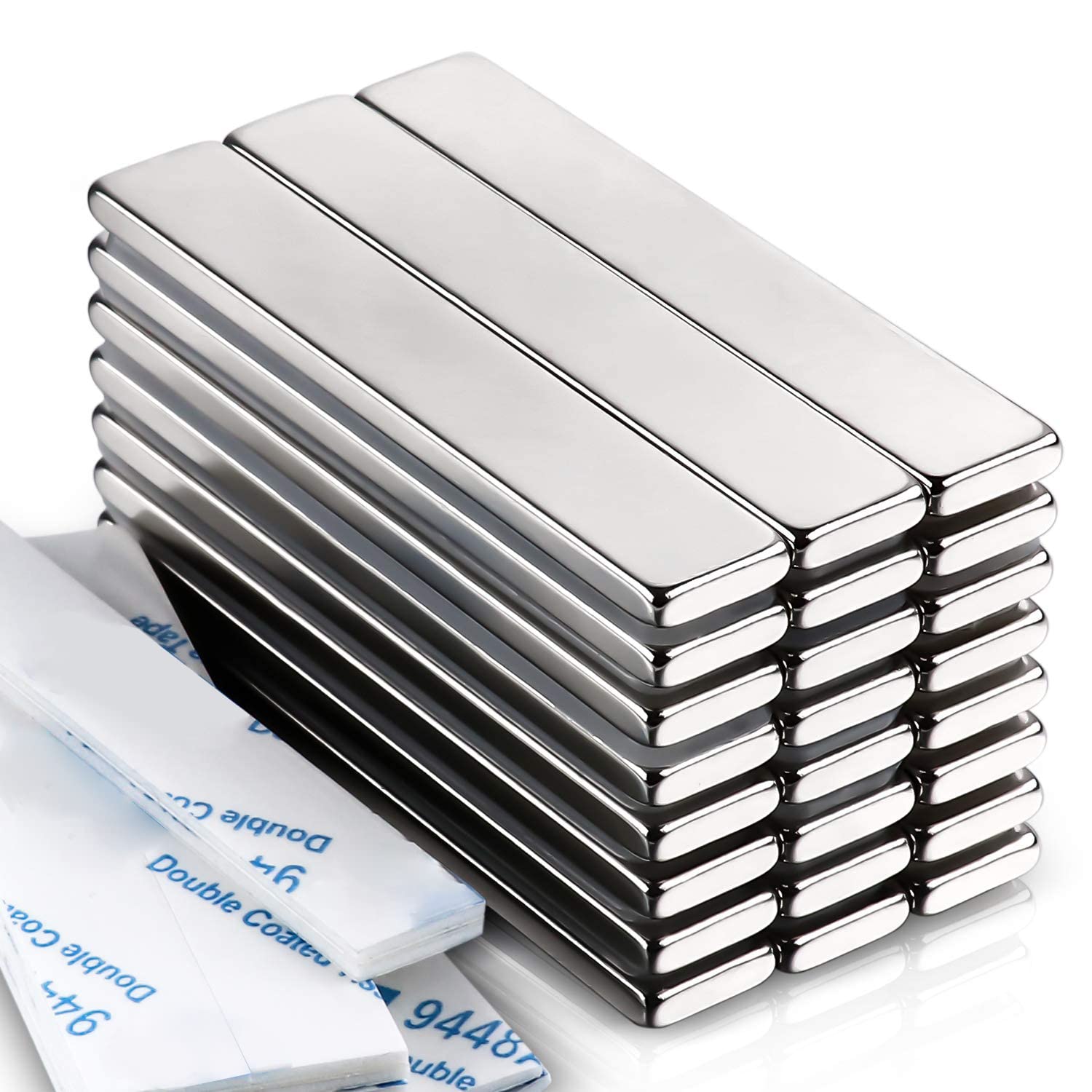
Helmet + Magnets
By installing a working, certified bike helmet into my design, I made the design safer for the road. The magnets connect the chin piece to the main helmet, to allow my head to go in and out of the helmet with ease.
On the left, you can see the helmet after being installed. I glued it in using plastic glue, and melted some excess printer material around the edges to solidify it and keep it in place. On the right, you can see the seam between the main helmet and the chin section. Connecting the two sections are 4 total 10*60*3mm neodymium magnets.
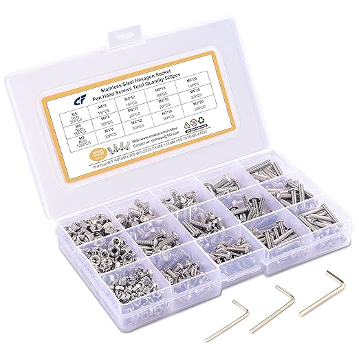
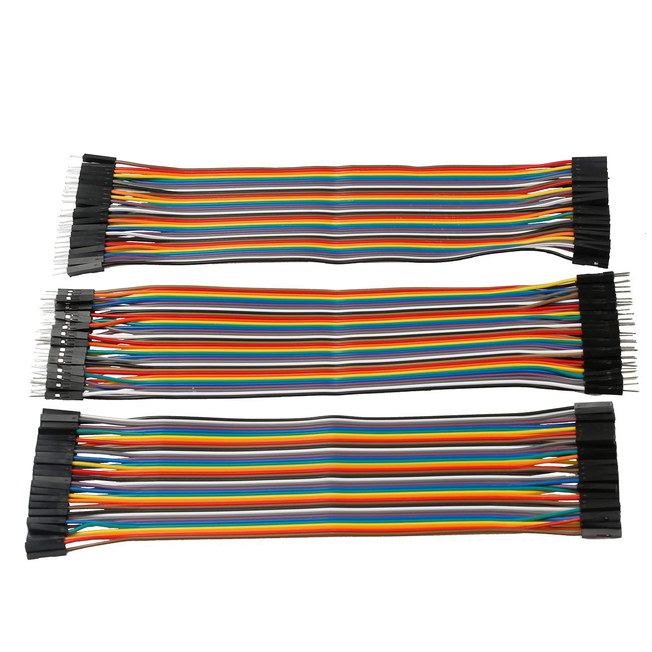
Servos + Electronics
To power the motion system, I use an Arduino Nano and 6 Micro MG90 Servos. It is powered by a 5V power bank. They move the Mask outwards in 3 pieces, allowing for easier verbal discussion with the mask on.
On the left, you can see the Arduino Nano with all wiring attached. You can see the 2 sets of signal wires, along with the 5V and ground wires. On the left. you can see one of the installation points of the servo motors on the front lower sides of the helmet. They move the two front panels to the side.
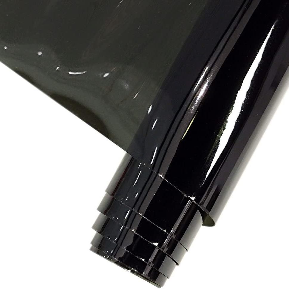
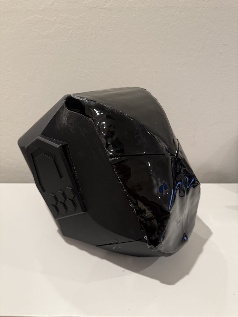
Padding + Vinyl
I added a few layers of padding in the helmet for a tighter, motorcycle helmet feel. The vinyl allows for me to see out of the helmet while maintaining a flat, precise look from the outside and covering my face from dust, debris and other objects in the air like rain.
On the left, the foam padding is visible. It is shaped to fit inside the cavities of the helmet. On the right, the process of applying the vinyl to the helmet can be visible. I use hot glue to apply it to the solid surfaces of the helmet, then cut of excess and seperation lines with a utility knife.
Next Steps
Peripheral Windows
I plan to cut out new viewing windows in the sides of the helmets to allow my peripheral vision to function as well as my frontal vision. It will make it safer especially when riding on busy roads.
Aesthetic Lighting
To increase the movie accuracy and “cool factor” I am planning to add red COB lights to pre-designed cutouts in the helmet. As seen on the right, these lights can also increase visibility at night, which is also when the helmet will often be used.
Explore the How to Guide
Learn how to build the helmet for yourself, without making the mistakes I had to. Have fun!